DOWNLOAD complete documentation, parts and distributers
DOWNLOAD schematic high voltage (EAGLE .sch)
DOWNLOAD schematic microcontroller (EAGLE .sch)
DOWNLOAD Software for microcontroller Atmel ATMega88
Schematics around counter tubes are mainly related to
the high voltage generation.
Examples are widely spread in the net. A special issue of this counter is beside the
generation of the high
voltage, the microcontroller computing the clicks and display
the data on an
LCD. Here the main features of this design:
- Software controlled speaker pulse width “click”
- Display of CPM and nSv/h
- Display of Li-ion and tube voltage
- Charging facility from a USB port
- Step up converter to a stable 5.0V
- Auto-power-off after 10min
- Li-ion accu deep discharge protection
- PWM-output for an external analog meter
Unfortunately the contrast varies with the supplying
voltages. The usage of a
standard 3.7 V Li-ion rechargeable battery is a
solution to the portability and
capacity. The annoying effect of
self-discharging like regular nickel metalhydrid
accus is avoided by usage of li-ion
technology. Recharging is supplied with a
simple USB cable from any computer
interface.
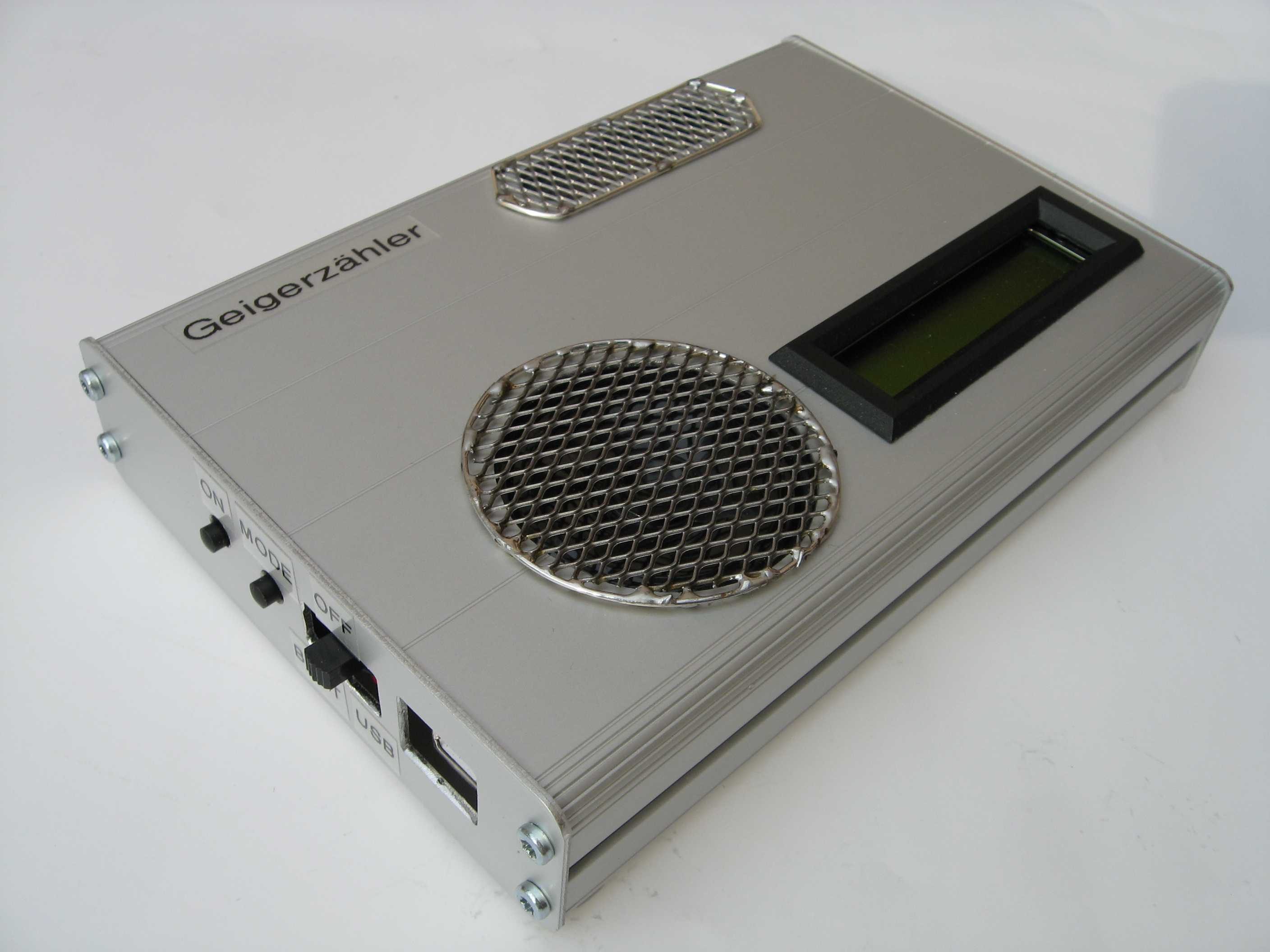
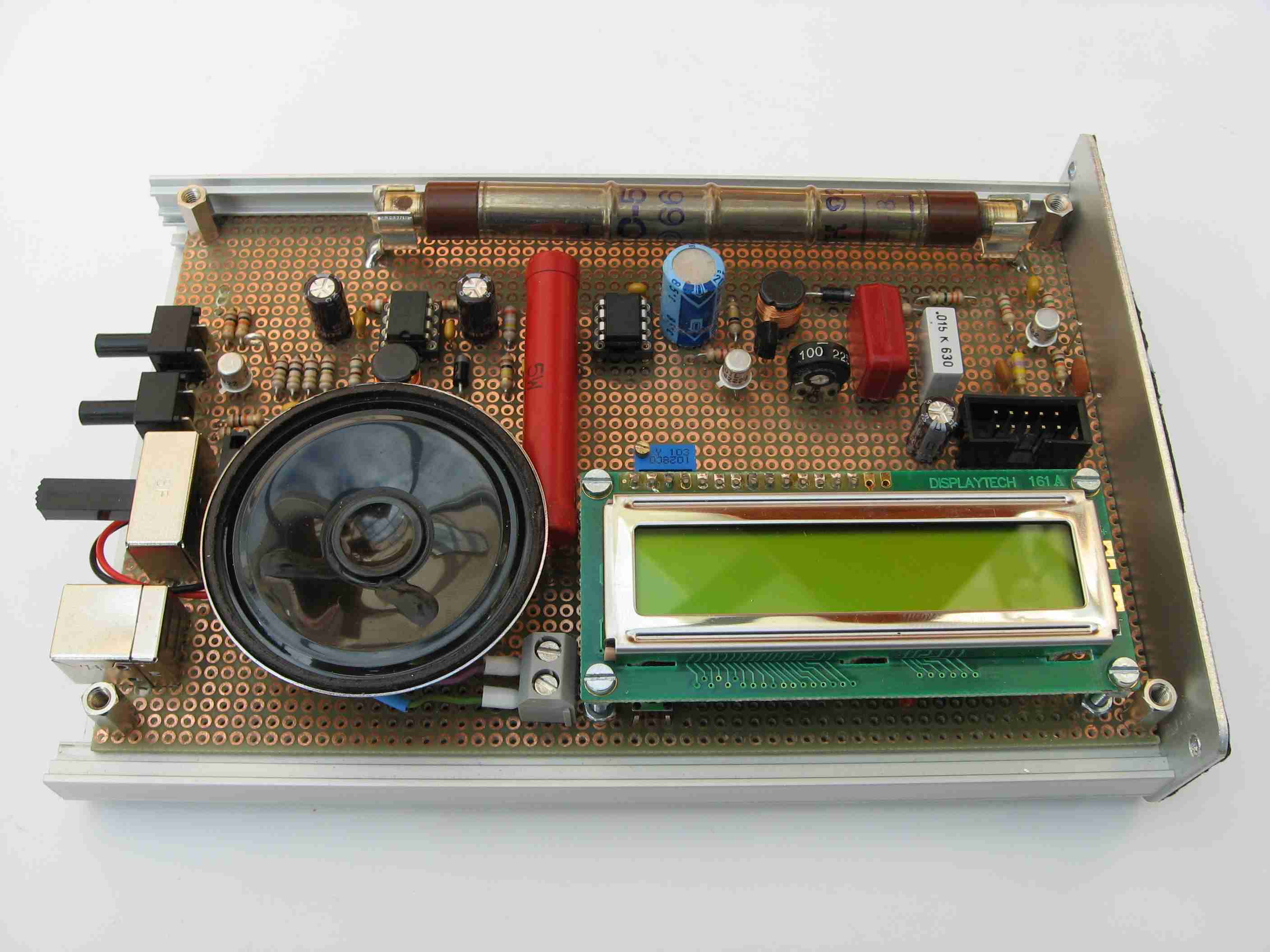
Figure 1: Geiger Counter Home Made Figure 2: PCB perf board
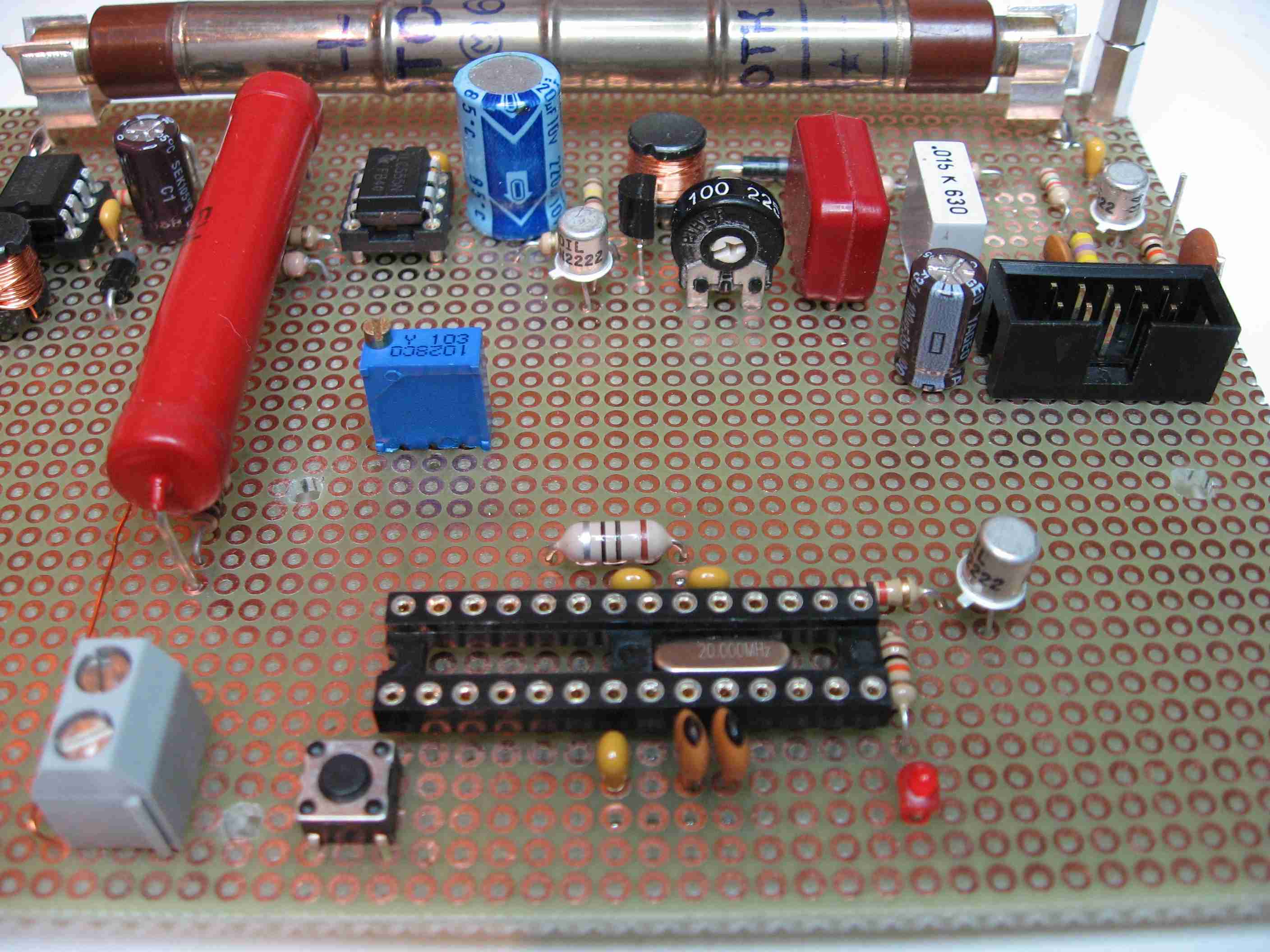
Figure 3: Socket of controller and high voltage part
The advantage of this high voltage circuit is the very low supply
current consumption and the independence of the supplying voltage.
R9 is the anode resistor for the tube. C2 and C3 are storage
capacitors for high voltage. R4 and C1 determine the on-time (30us),
C1 and R3 the off-time (3ms). During the on pulse, the current in the
coil increases with about 1mA / ms. R2 and the Ube limits the current
at 25mA and switches the Q2 off. In this moment the L1 in combination
with stray capacitance creates a 1/2 sine voltage wave about 2us long
and >400V high. This is passed by D2 to the storage capacitors C3 & C4.
This is an unwanted effect when switching a relay coil with a transistor.
This spike destroys the transistor if a freewheeling diode across the
coil is not implemented. See figure 4.
For a more detailed description see Tom Napier [1] and John Giametti [2].
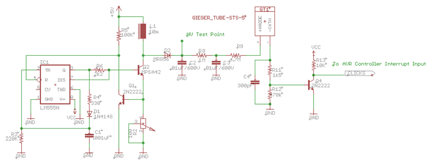
Figure 4: Schematic high voltage generation
interrupt input it passes a low pass filter R10 and C5. R13 and R14 are the voltage
divider for the 400V high voltage. The ratio is 1GΩ by 1MΩ. The high values are
necessary since the high voltage is of very high impedance. Lower values would
affect the measurement accuracy. The HV signal is connected to the A/D converter
ADC1 of the controller. The battery voltage 3.7V is applied to the ADC0 with a divider
of R11 and R12. Since the internal reference voltage for the A/D converter is 1.1 volt
a reduction is necessary. A software calibration value will compensate for this.
S2 is the pushbutton for the display mode. The interrupt input INT1 is falling edge
sensitive. The RC combination debounces the switch.
The PB2 output drives the SPEAKER signal. T1 decouples and amplifies for the
8Ω speaker. The timer2 output compare (OC1A) pin is the PWM signal for the
analog meter. R4 limits the maximum current. For other than 100uA full scale meters
the value has to be adjusted. With a current of 100uA full scale the instrument is
calibrated to about 4000 CPM respective 22000nSv/h. For higher currents an
additional stage is necessary.
LED1 flashes with 0.5 Hz. A compare match of timer1 it toggles the LED and the
flag for the main program loop is set.
S3 selects the power source either from the Li-ion cell or from an USB interface.
In this case the battery charges.
X1 is the ISP (in circuit programming) connector.
CAUTION: When programming, keep power button pressed. During programming
the reset pin is kept low and the controller switches it own power off. See figure 4.
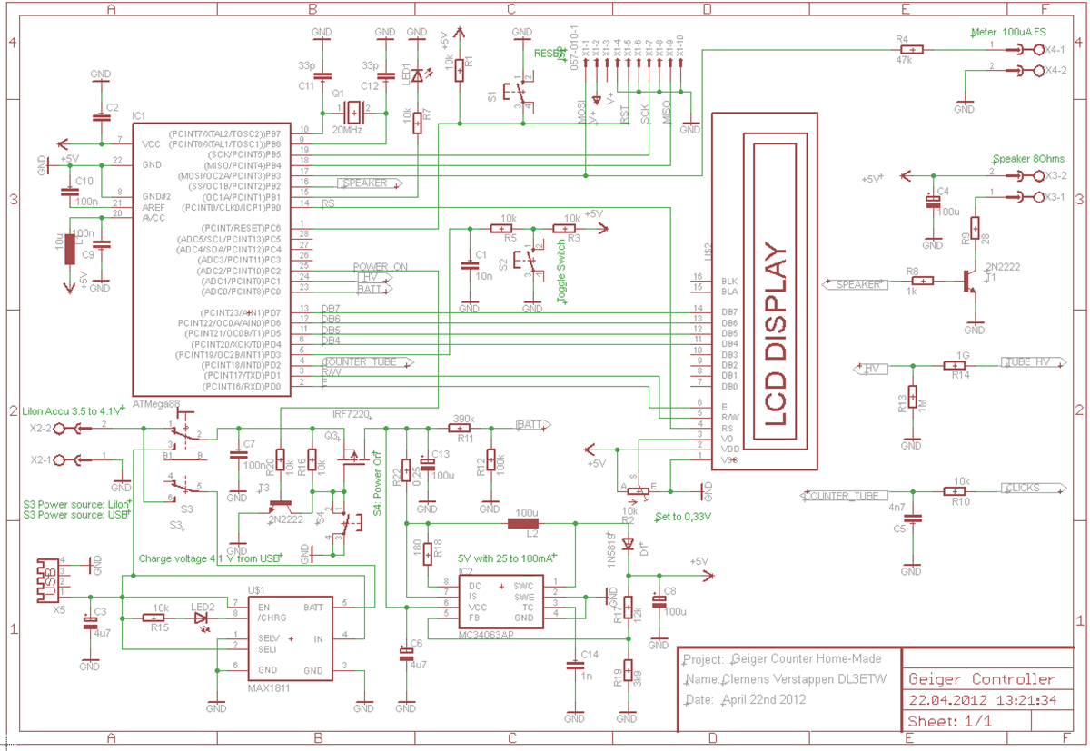
Figure 4: Schematic microcontroller
References:
[1] Napier,
Tom. Biassing G-M Tubes Isn´t So Hard, Nuts&Volts January 2004, www.nutsvolts.com
[2] DIY Geiger Counter, http://sites.google.com/site/diygeigercounter/
[4] Reichelt Elektronik GmbH & Co KG,
Tel. +49 44 22 - 9 55-3 33, http://www.reichelt.de: standard
components.
[5] Wagner, D. , DJ7BU: Selbstbau eines Geigerzählers. Funkamateur 61 (2012) H. 2, S. 154-157; http://www.funkamateur.de
[6] BERTHOLD TECHNOLOGIES
GmbH & Co. KG, Tel. +49 7081 177-0 http://www.berthold.com
[7]
Pintschka , F.: Uranglazuren http://www.frank-pintschka.de/3.html
[8] International System of Units http://en.wikipedia.org/wiki/International_System_of_Units
http://de.wikipedia.org/wiki/Internationales_Einheitensystem
[9] Conrad Electronic SE, Tel.:
0180 5 312111, http://www.conrad.de/ce/